| front1.jpg |
Front 1 - Main components of front headquarters
|
|
| front2.jpg |
Front 2 Front headquarters - staff
|
|
| front3.jpg |
Front 3 Front headquarters -chiefs of arms and services
|
|
| front4.jpg |
Front 4 Front command post support elements
|
|
| front5.jpg |
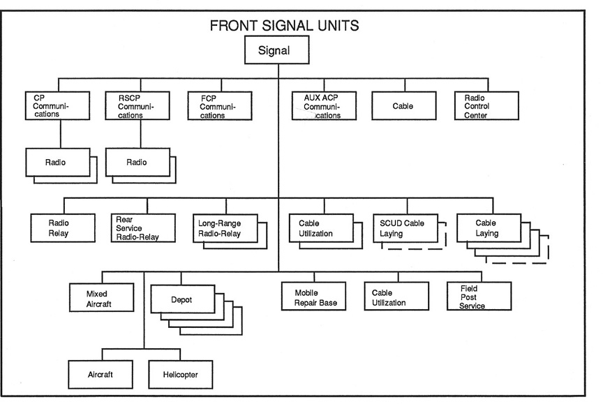
Front 5 Front signal units
|
|
| front6.jpg |
Front 6 Front units and formations
|
|
| front7.jpg |
Front 7 Combined arms army organization
|
|
| front8.jpg |
Front 8 Tank army organization
|
|
| front9.jpg |
Front 9 Air army organization
|
|
| front10.jpg |
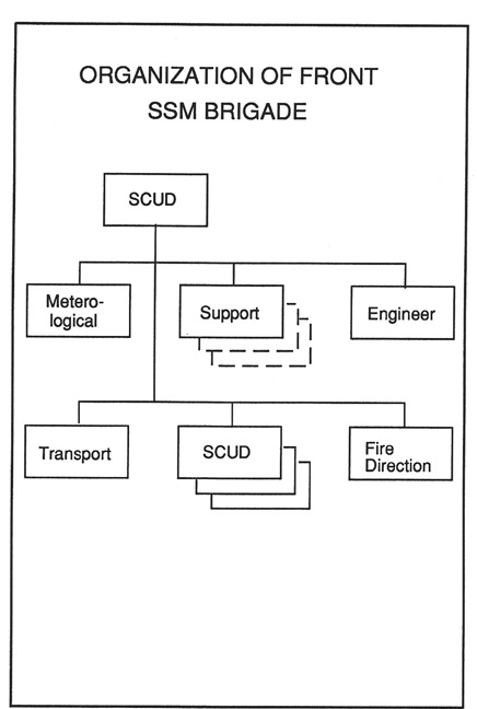
Front 10 Front surface to surface missile brigade
|
|
| front11.jpg |
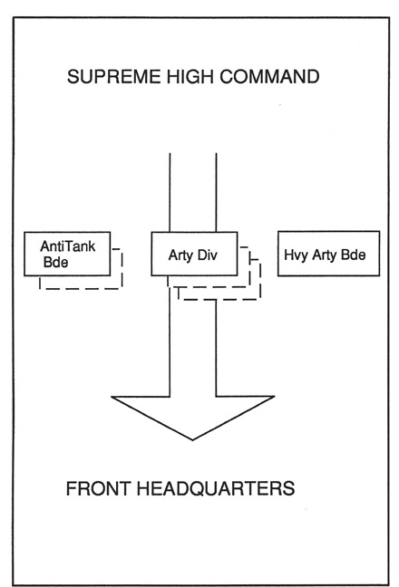
Front 11 Supreme High Command artillery units
|
|
| front12.jpg |
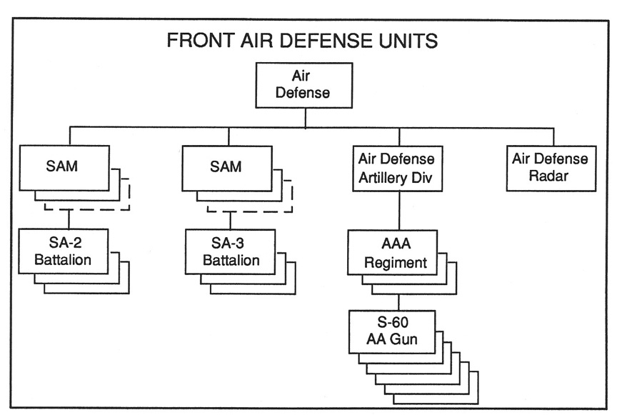
Front 12 Front air defense units
|
|
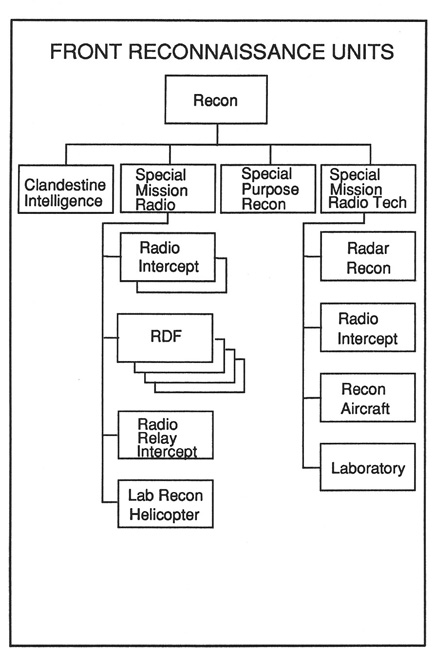
| front13.jpg |
Front 13 Front reconnaissance units
|
|
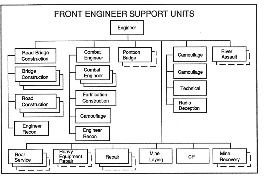
| front14.jpg |
Front 14 Front engineer units
|
|
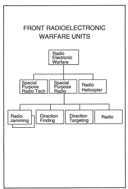
| front15.jpg |
Front 15 Front radio electronic warfare units
|
|
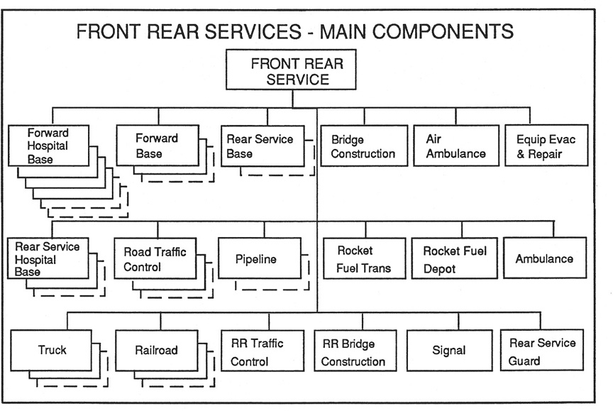
| front16.jpg |
Front 16 Main components of front rear services
|
|
| front17.jpg |
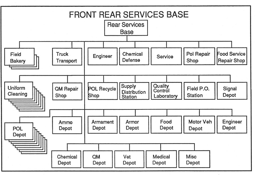
Front 17 Front rear services base
|
|
| front18.jpg |
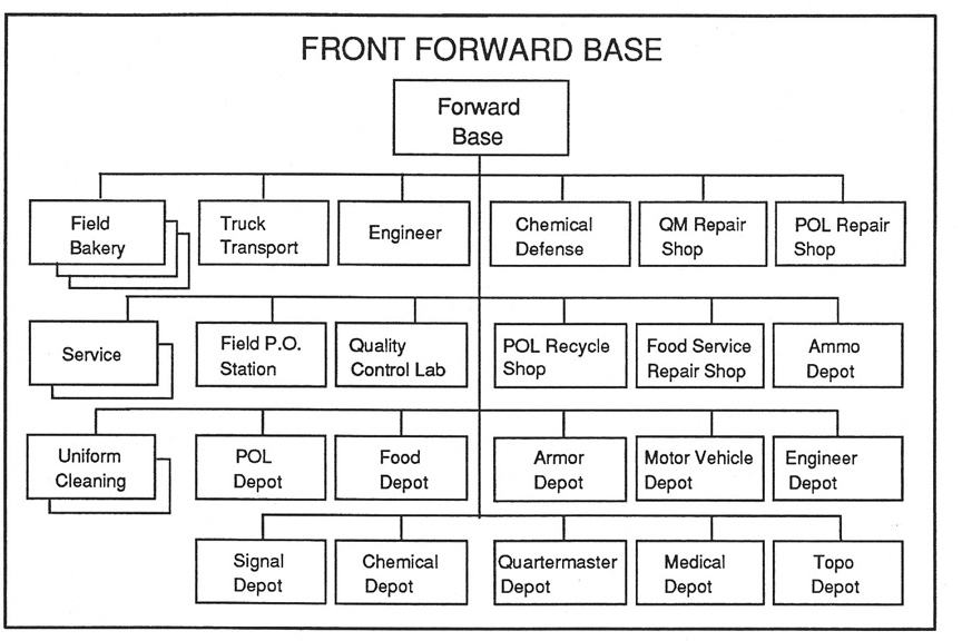
Front 18 Front forward base
|
|
| front19.jpg |
Front 19 Front rear service rear hospital base
|
|
| front20.jpg |
Front 20 Front rear service forward hospital base
|
|
| front21.jpg |
Front 21 Front motor transport brigade
|
|
| front22.jpg |
Front 22 Front railroad brigade
|
|
| front23.jpg |
Front 23 Front traffic control brigade
|
|
| front24.jpg |
Front 24 Front pipeline brigade
|
|
| front25.jpg |
Front 25 Front bridge construction brigade
|
|
| front26.jpg |
Front 26 Front repair and evacuation units
|
|
| front27.jpg |
Front 27 Front security division
|
|
| front28.jpg |
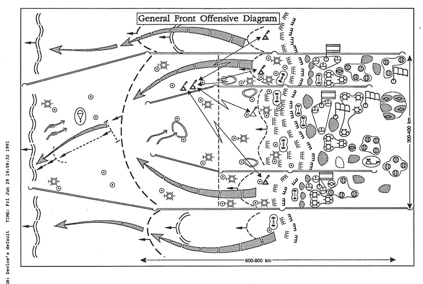
Front 28 Schematic diagram front offensive operation
|
|
| front29.jpg |
Front 29 Schematic diagram front nuclear war - dividing enemy
into groups
|
|
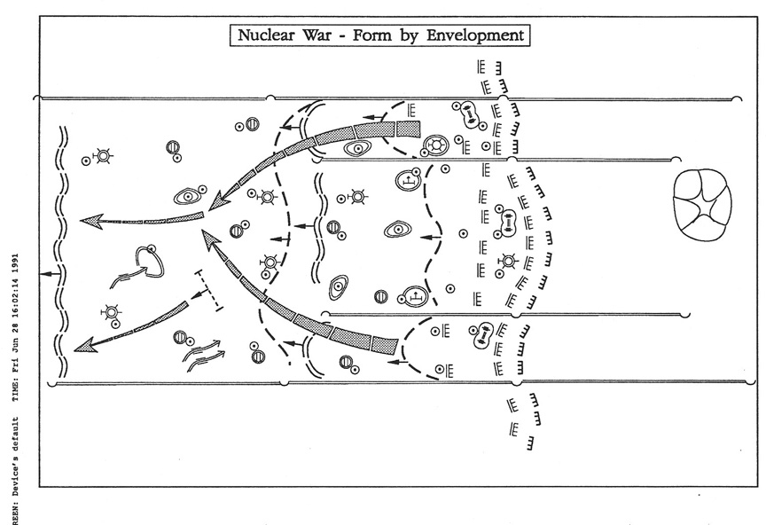
| front30.jpg |
Front 30 Schematic diagram front nuclear war - double
envelopment
|
|
| front31.jpg |
Front 31 Schematic diagram front nuclear war - combined methods
|
|
| front32.jpg |
Front 32 Schematic diagram front nuclearwar - envelopment
against an obstacle
|
|
| front33.jpg |
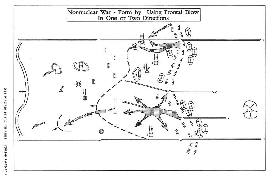
Front 33 Schematic diagram front non-nuclear war - frontal blow
in two directions
|
|
| front34.jpg |
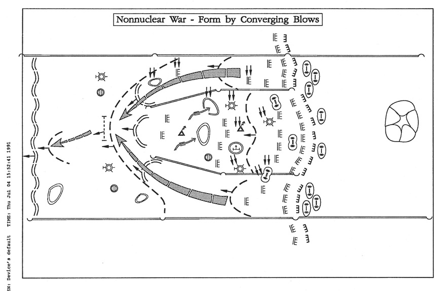
Front 34 Schematic diagram front non-nuclear war - converging
blows
|
|
| front35.jpg |
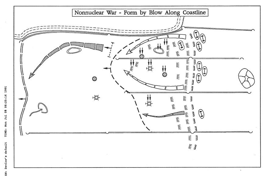
Front 35 Schematic diagram front non-nuclear war - blow along a
coastline
|
|
| front36.jpg |
Front 36 Schematic diagram division defensive positions
|
|
| front37.jpg |
Front 37 Schematic diagram army defensive positions
|
|
| front38.jpg |
Front 38 Schematic diagram front defensive positions
|
|
| front39.jpg |
Front 39 Schematic diagram conterattack by division second echelon
|
|
| front40.jpg |
Front 40 Schematic diagram counterattack by army second echelon
|
|
| front41.jpg |
Front 41 Schematic diagram counterattack by front reserve
|
|
| front42.jpg |
Front 42 Schematic diagram air army missions in initial nuclear strike
|
|
| front43.jpg |
Front 43 Schematic diagram air army missions to cover rear service
targets
|
|
| front44.jpg |
Front 44 Schematic diagram air army missions in counter air
|
|
| front45.jpg |
Front 45 Schematic diagram air army missions in support of ground
troops
|
|
| front46.jpg |
Front 46 Schematic diagram air army plan for front operation
|
|
| front47.jpg |
Front 47 Schematic diagram front air army - troop control system
|
|
| front48.jpg |
Front 48 Artillery division
|
|
| front49.jpg |
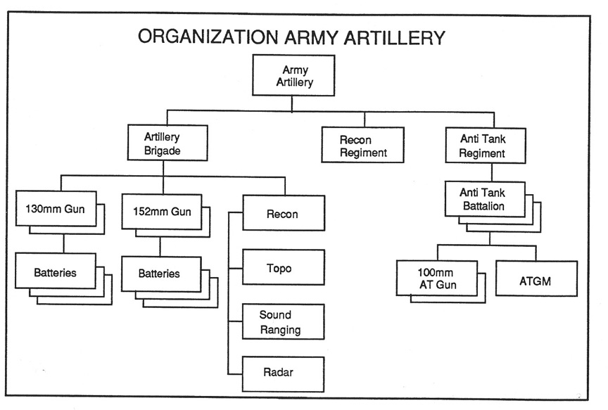
Front 49 Army artillery
|
|
| front50.jpg |
Front 50 Army anti-tank regiment
|
|
| front51.jpg |
Front 51 Division artillery regiment
|
|
| front52.jpg |
Front 52 Division multiple rocket launcher battalion
|
|
| front53.jpg |
Front 53 Division anti-tank battalion
|
|
| front54.jpg |
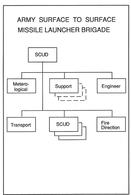
Front 54 Army surface to surface missile launcher brigade
|
|
| front55.jpg |
Front 55 Division free rocket battalion
|
|
| front56.jpg |
Front 56 Schematic diagram front air defense plan
|
|
| front57.jpg |
Front 57 Schematic diagram interaction of fighter air and SAM units -
vertical
|
|
| front58.jpg |
Front 58 Schematic diagram interaction of fighter air and SAM units -
horizontal
|
|
| front59.jpg |
Front 59 Motor rifle division
|
|
| front60.jpg |
Front 60 Tank division
|
|
| front61.jpg |
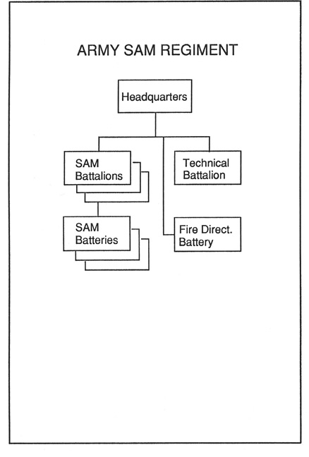
Front 61 Army air defense missile regiment
|
|
| front62.jpg |
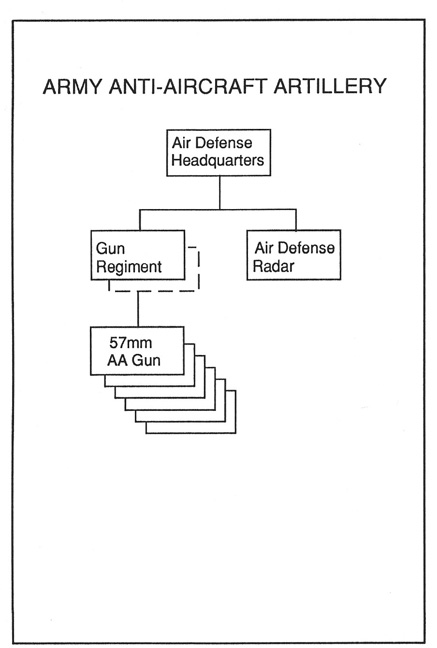
Front 62 Army antiaircraft artillery units
|
|
| front63.jpg |
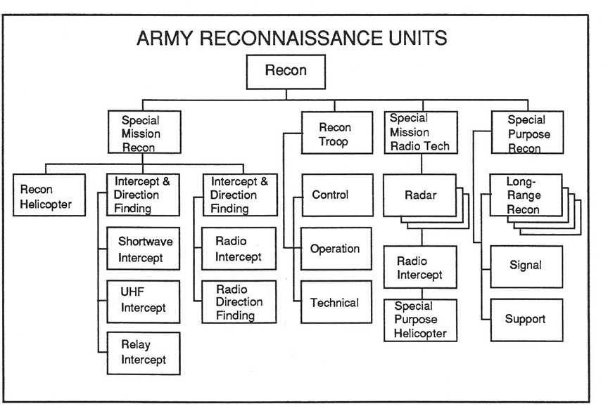
Front 63 Army reconnaissance units
|
|
| front64.jpg |
Front 64 Army reconnaissance troops of arms of service and special
troops
|
|
| front65.jpg |
Front 65 Army chemical warfare troops units
|
|
| front66.jpg |
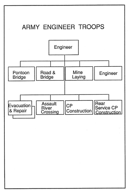
Front 66 Army engineer troops
|
|
| front67.jpg |
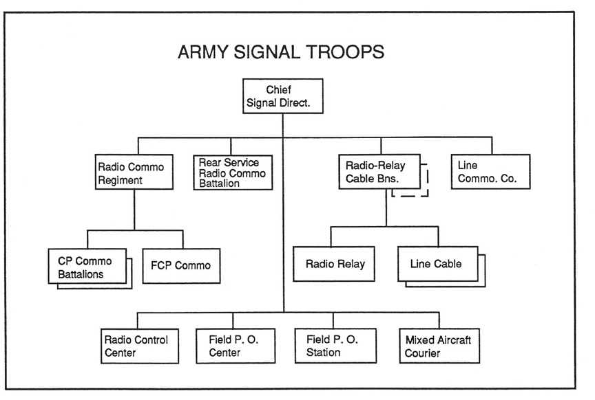
Front 67 Army signal troops
|
|
| front68.jpg |
Front 68 Army radio electronic combat troops
|
|
| front69.jpg |
Front 69 Schematic diagram army combat disposition for offensive
|
|
| front70.jpg |
Front 70 Schematic diagram army - nuclear war - conduct of offensive
|
|
| front71.jpg |
Front 71 Schematic diagram army - nuclear war - envelopment
|
|
| front72.jpg |
Front 72 Schematic diagram army -nuclear war - encirclement
|
|
| front73.jpg |
Front 73 Schematic diagram army - committing second echelon division
|
|
| front74.jpg |
Front 74 Schematic diagram army - non-nuclear war - penetration
|
|
| front75.jpg |
Front 75 Schematic diagram army - non-nuclear war - encirclement
|
|
| front76.jpg |
Front 76 Schematic diagram army - attack against hasty prepared defense
|
|
| front77.jpg |
Front 77 Schematic diagram army - coordinated encirclement with two
armies
|
|
| front78.jpg |
Front 78 Soviet map symbols sheet 1
|
|
| front79.jpg |
Front 79 Soviet map symbols sheet 2
|
|
| front80.jpg |
Front 80 Soviet map symbols sheet 3
|
|
| front81.jpg |
Front 81 Schematic diagram Artillery against counterattack
|
|
| front82.jpg |
Front 82 Schematic diagram artillery successive concentrations of fire
|
|
| front83.jpg |
Front 83 Schematic diagram artillery fire curtain or rolling barrage
|
|
| front84.jpg |
Front 84 Nomogram for calculating artillery fire against prepared
positions
|
|
| front85.jpg |
Front 85 Nomogram for determining required number of anti-tank weapons
|
|
| |
Chaonehbk Figure 1 - Basic elements of headquarters organization
|
|
| |
Chaonehbk Figure 2 - General form of command and special subordination
|
|
| |
Chaonehbk Figure 3 - Locations of command posts
|
|
| |
Chaonehbk Figure 4 - Forms of offensive operation
|
|
| |
Chaonehbk Figure 5 - Relation of missions in time and space
|
|
| |
Chaonehbk Figure 6 - Counterattacks
|
|
| |
Chaonehbk Figure 7 - National unit coefficients
|
|
| |
Chaonehbk Figure 8 - Sample probabilities table
|
|
| |
Chaonehbk Figure 9 - Division attack option one
|
|
| |
Chaonehbk Figure 10 - Division attack option two
|
|
| |
Chaonehbk Figure 11 - Division atack option three
|
|
| |
Chaonehbk Figure 12 - Movement from garrison
|
|
| |
Chatwohbk Figure 13 - Division Headquarters organization
|
|
| |
Chatwohbk Figure 14 - Division main Command post
|
|
| |
Chatwohbk Figure 15 - Division Forward Command post
|
|
| |
Chatwohbk Figure 16 - Division Rear Command post
|
|
| |
Chatwohbk Figure 17 - Signal Diagram
|
|
| |
Chatwohbk Figure 18 - Division Signal units
|
|
| |
Chatwohbk Figure 19 - Process of decision making (1)
|
|
| |
Chatwohbk Figure 20 - Process of decisio nmaking (2)
|
|
| |
Chatwohbk Figure 21 - Correlation of Forces table
|
|
| |
Chatwohbk Figure 22 - Description of meeting engagement
|
|
| |
Chatwohbk Figure 23 - Division planning exercise - current situation
|
|
| |
Chatwohbk Figure 24 - Division planning exercise - forcast situation
|
|
| |
Chatwohbk Figure 25 - Regiment Staff
|
|
| |
Chatwohbk Figure 26 - Regiment command post
|
|
| |
Chatwohbk Figure 27 - Regimental signal company
|
|
| |
Chatwohbk Figure 28 - Table for planning time
|
|
| |
Chatwohbk Figure 29 - Regiment in division meeting engagement
|
|
| |
Chatwohbk Figure 30 - Diagram of meeting engagement
|
|
| |
Chatwohbk Figure 31 - Diagram of motor rifle battalion in attack
|
|
| |
Chatwohbk Figure 32 - Diagram of regiment in attack
|
|
| |
Chathreehbk Figure 33 - Army Staff
|
|
| |
Chathreehbk Figure 34 - Army main Command post
|
|
| |
Chathreehbk Figure 35 - Army Forward Command post
|
|
| |
Chathreehbk Figure 36 - Army Rear Command post
|
|
| |
Chathreehbk Figure 37 - Army Headquarters Support Troops
|
|
| |
Chathreehbk Figure 38 - Army Signal Troops
|
|
| |
Chathreehbk Figure 39 - Army Planning Documents
|
|
| |
Chathreehbk Figure 40 - Map of Army Operations
|
|
| |
Chafourhbk Figure 41 - Front Headquarters
|
|
| |
Chafourhbk Figure 42 - Main components of front headquarters
|
|
| |
Chafourhbk Figure 43 - Front command post and direct support
elements
|
|
| |
Chafourhbk Figure 44 - Front signal units
|
|
| |
Chafourhbk Figure 45 - Front communications system
|
|
| |
Chafourhbk Figure 46 - Airborne command posts
|
|
| |
Chafourhbk Figure 47 - Army mobile command post vehicle
|
|
| |
Chafourhbk Figure 48 - Front mobile command post vehicle
|
|
| |
Chafourhbk Figure 49 - Front command post composition
|
|
| |
Chafourhbk Figure 50 - Front command post dimensions
|
|
| |
Chafourhbk Figure 51 - Front (army) command post schematic
|
|
| |
Chafourhbk Figure 52 - Schematic layout of front air army
control system
|
|
| |
Chafourhbk Figure 53 - Front planning documents
|
|
| |
Chafourhbk Figure 54 - Table of movement of aviation units
|
|
| |
Normfig Figure 55 - Norms for times to accomplish tasks
|
|
| |
Normfig Figure 56 - Norms for average rate of advance
|
|
| |
Normfig Figure 57 - Norms for density of defense
|
|
| |
Normfig Figure 58 - Norms for locations
|
|
| |
Normfig Figure 59 - Diagram of division offensive norms
|
|
| |
Normfig Figure 60 - Diagram of front offensive planning factors
|
|
| |
Normfig Figure 61 - Combat reconnaissance units
|
|
| |
Normfig Figure 62 - Limits of visual observation
|
|
| |
Normfig Figure 63 - Aerial Reconnaissance
|
|
| |
Normfig Figure 64 - Drone reconnaissance aircraft
|
|
| |
Normfig Figure 65 - Visual reconnaissance range
|
|
| |
Normfig Figure 66 - Artillery reconnaissance
|
|
| |
Normfig Figure 67 - Preparation time for reconnaissance report
|
|
| |
Normfig Figure 68 - Tactical-technical characteristics of transport
aircraft
|
|
| |
Normfig Figure 69 - Echeloning material reserves of the front
|
|
| |
Normfig Figure 70 - Norms for material reserves in the army
|
|
| |
Normfig Figure 71 - Requirements for material reserves in offensive
|
|
| |
Normfig Figure 72 - Operational expenditure and reserves
|
|
| |
Normfig Figure 73 - Location of rear supply and support elements
|
|
| |
Normfig Figure 74 - Protection against radiation
|
|
| |
Normfig Figure 75 - Coefficients of reduction of radiation
|
|
| |
Normfig Figure 76 - Movement data for tracked and wheeled vehicles
|
|
| |
Normfig Figure 77 - Average speed of march and length of daily march
|
|
| |
Normfig Figure 78 - Times to form unit column
|
|
| |
Normfig Figure 79 - Distances between column elements
|
|
| |
Normfig Figure 80 - March, halt, and rest durations
|
|
| |
Normfig Figure 81 - General character of tactical calculations
|
|
| |
Normfig Figure 82 - Nomogram for calculating duration of a march
|
|
| |
Normfig Figure 83 - Nomogram for calculating duration of movement from
assembly area to start line
|
|
| |
Normfig Figure 84 - Nomogram for calculating time required for mobile
column to deply into new area
|
|
| |
Normfig Figure 85 - Form to calculate time unit is in new area
|
|
| |
Normfig Figure 86 - Form for calculating duration of march
|
|
| |
Normfig Figure 87 - Form to calculate required rate of travel
|
|
| |
Normfig Figure 88 - Calculation of duration of march over complex route
|
|
| |
Normfig Figure 89 - Nomogram for calculating length of mobile formation
consisting of several columns
|
|
| |
Normfig Figure 90 - Nomogram to calculate time required to pass narrow
spot on route
|
|
| |
Normfig Figure 91 - Nomogram to calculate time required to pass
difficult section of route
|
|
| |
Normfig Figure 92 - Nomogram to calculate time head and tail of column
will pass regulation point
|
|
| |
Normfig Figure 93 - Nomogram to calculate time and distance to point of
meeting engagement
|
|
| |
Normfig Figure 94 - Calculation of time to advance and deploy into the
attack from line of march
|
|
| |
Normfig Figure 95 - Form for calculation of expected time and location
of meeting engagement
|
|
| |
Normfig Figure 96 - Nomogram for calculating expected time and speed to
overtake retreating enemy
|
|
| |
Normfig Figure 97 - Nomogram to calculate time available to plan fire
on advancing enemy
|
|
| |
Normfig Figure 98 - Calculation of duration of operation in one
location
|
|
| |
Normfig Figure 99 - Nomogram for calculating the combined effectiveness
of several systems
|
|
| |
Normfig Figure 100 - Coefficients of comensurability
|
|
| |
Normfig Figure 101 - Expected losses
|
|
| |
Normfig Figure 102 - Nomogram to determine required enemy losses to
achieve correlation of forces
|
|
| |
Normfig Figure 103 - Nomoram relating corelation of forces to rate of
advance (1)
|
|
| |
Normfig Figure 104 - Nomogram relating correlation of forces to rate of
advance (2)
|
|
| |
Normfig Figure 105 - Force attrition nomogram - army
|
|
| |
Normfig Figure 106 - Force attrition nomogram - front
|
|
| |
Normfig Figure 107 - Table for calculating restoration of combat
effectiveness
|
|
| |
Normfig Figure 108 - Form for calculating expected radiation doses
|
|
| |
Normfig Figure 109 - Nomogram for calculating expected radiation dose
|
|
| |
Normfig Figure 110 - Table to enter description of travel routes
|
|
| |
Normfig Figure 111 - Graph of effectiveness of alternate routes
|
|
| |
Normfig Figure 112 - Table of effectiveness indicators for march routes
|
|
| |
Normfig Figure 113 - Table of effectiveness of artillery fire on
targets
|
|
| |
Normfig Figure 114 - Table of effectiveness of artillery fire on
targets
|
|
| |
Normfig Figure 115 - Table of effectiveness of artillery fire on
targets
|
|
| |
Normfig Figure 116 - Form for calculating weapons effectiveness
|
|
| |
Normfig Figure 117 - Form for calculating probabillity of target
detection
|
|
| |
Normfig Figure 118 - Form for calculating search length
|
|
| |
Normfig Figure 119 - Nomogram for calculating probability of target
detection
|
|
| |
Normfig Figure 120 - Value of coefficient
|
|
| |
Normfig Figure 121 - Nomogram to determine quantity of march routes
|
|
| |
Normfig Figure 122 - Conditions of formation shift (a) and deployment
(b) of columns on a march
|
|
| |
Normfig Figure 123 - Formation change of columns into movement
|
|
| |
Normfig Figure 124 - Relationship between speed, time, and distance
required for columns to move from sequence head-to-tail into line abreast
|
|
| |
Normfig Figure 125 - Values of coefficient K
|
|
| |
Normfig Figure 126 - Types of fire and their use
|
|
| |
Normfig Figure 127 - Diagram of successive concentration of fire
|
|
| |
Normfig Figure 128 - Diagram of fire curtain or rolling barrage
|
|
| |
Normfig Figure 129 - Time to relocate artillery
|
|
| |
Normfig Figure 130 - Composition of artillery groups
|
|
| |
Normfig Figure 131 - Artillery preparatory fire
|
|
| |
Normfig Figure 132 - Artillery density norms for breakthrough
|
|
| |
Normfig Figure 133 - Width of front covered by anti-tank units
|
|
| |
Normfig Figure 134 - Artillery norms for guns versus targets
|
|
| |
Normfig Figure 135 - Rocket unit locations
|
|
| |
Normfig Figure 136 - Safe distances from nuclear explosions
|
|
| |
Normfig Figure 137 - Technical data for rockets
|
|
| |
Normfig Figure 138 - Estimated units of fire (BK)
|
|
| |
Normfig Figure 139 - Form for calculation of artillery capability
|
|
| |
Normfig Figure 140 - Nomogram for calculating artillery fire against
enemy personnel and weapons
|
|
| |
Normfig Figure 141 - Nomogram for calculating the required number of
anti-tank weapons
|
|
| |
Normfig Figure 142 -
|
|
| |
Normfig Figure 143 - Nomogram to calculate time required to shift
positions
|
|
| |
Normfig Figure 144 - Example artillery fire ammunition totals
|
|
| |
Normfig Figure 145 - Sample list of command post areas
|
|
| |
Normfig Figure 146 - Sample table for calculating fire
|
|
| |
Normfig Figure 147 - Target list for preparatory fire
|
|
| |
Normfig Figure 148 - Targets for artillery fire
|
|
| |
Normfig Figure 149 - Calculation of artillery requirements
|
|
| |
Normfig Figure 150 - Example division artillery requirement
|
|
| |
Normfig Figure 151 - Sample calculation of artillery fire
|
|
| |
Normfig Figure 152 - Sample artillery fire for assault support
|
|
| |
Normfig Figure 153 - Target area neutralized by 122mm how battalion
|
|
| |
Normfig Figure 154 - Firing capabilities 152 howitzer
|
|
| |
Normfig Figure 155 - Number of Artillery batteries to neutalize targets
|
|
| |
Normfig Figure 156 - Norms for shell expenditure to barrages
|
|
| |
Normfig Figure 157 - Conversion coefficients - artillery
|
|
| |
Normfig Figure 158 - Average expenditure artillery battery
|
|
| |
Normfig Figure 159 - Breakdown of division ammunition supply
|
|
| |
Normfig Figure 160 - Norms to neutralze artillery battery
|
|
| |
Normfig Figure 161 - Fire assaults and fire concentrations
|
|
| |
Normfig Figure 162 - Sample target areas for division CP's
|
|
| |
Normfig Figure 163 - Norms for neutralization
|
|
| |
Normfig Figure 164 - Artillery and mortar units of fire
|
|
| |
Normfig Figure 165 - Predicted bombardment of unobserved strong point
|
|
| |
Normfig Figure 166 - Ammunition norms for neutralization of SP
artillery
|
|
| |
Normfig Figure 167 - Norms - average ammunition required to neutralize
|
|
| |
Normfig Figure 168 - Minimum number 152 Gun-How to neutralize artillery
battery
|
|
| |
Normfig Figure 169 - Norm- ammunition required to neutralize SP
artillery
|
|
| |
Normfig Figure 170 - Artillery required to neutralize one battery
|
|
| |
Normfig Figure 171 - Required guns to destroy missile launcher
|
|
| |
Normfig Figure 172 - Ammunition expenditure norm for stationary targets
|
|
| |
Normfig Figure 173 - Ammunition norm against well prepared defense
strong point
|
|
| |
Normfig Figure 174 - Norm - ammunition to neutralize SP artillery
|
|
| |
Normfig Figure 175 - Probability against hastily occupied strong point
|
|
| |
Normfig Figure 176 - Probability against hastily occupied strong point
|
|
| |
Normfig Figure 177 - Rate of fire for various artillery pieces
|
|
| |
Normfig Figure 178 - Rate of fire for mortars
|
|
| |
Normfig Figure 179 - Average reaction time for artillery to fire orders
|
|
| |
Normfig Figure 180 - Rate of fire for multiple rocket launchers
|
|
| |
Normfig Figure 181 - Locatins of artillery deployment
|
|
| |
Normfig Figure 182 - Area of maximum effect for artillery fire
|
|
| |
Normfig Figure 183 - Time required for artillery to relocate
|
|
| |
Normfig Figure 184 - Ammunition expenditure norms against unobserved
targets
|
|
| |
Engstrans Figure 185 - Nomogram to calculate duration of crossing
obstacle with ferrying equipment
|
|
| |
Engstrans Figure 186a - Form to calculate the duration of a river
crossing of sub-units on amphibious crossing equipment-
|
|
| |
Engtrans Figure 186b - Form to calculate the duration of a river
crossing of sub-units on amphibious crossing equipment
|
|
| |
Engtrans Figure 187 - Nomogram to calculate tank crossing under water
|
|
| |
Engtrans Figure 188 - Nomogram for calculating duration of crossing a
water obstacle
|
|
| |
Engtrans Figure 189 - Form to calculatemanpower and equipment for
fortification construction
|
|
| |
Engtrans Figure 190 - Nomogram for calculating mine fields
|
|
| |
Engtrans Figure 191 - Form to calculate tranportation requirement
|
|
| |
Engtrans Figure 192 - Table to calculate time to transport given load
|
|
| |
Engtrans Figure 193 - Table to calculate duration of rail movement
|
|
| |
Engtrans Figure 194 - Form to calculate required number of aircraft
|
|
| |
Engtrans Figure 195 - Nomogram for determining fuel requirements
|
|
| |
Engtrans Figure 196 - Nomogram to determine traffic capacity of route
|
|
| |
Chasixhbk Figure 197 - Message Journal
|
|
| |
Chasixhbk Figure 198 - Table of daily staff activity
|
|
| |
Chasixhbk Figure 199 - Combat daily duty chart (front)
|
|
| |
Chasixhbk Figure 200 - Diagram of commander - staff interaction
|
|
| |
Chasixhbk Figure 201 - Form for distribution of support forces
|
|
| |
Chasixhbk Figure 202 - Availability of Time and use of Chemical and
Nuclear Weapons
|
|
| |
Chasixhbk Figure 203 - Destruction of Targets in First Nuclear Strike
|
|
| |
Chasixhbk Figure 204 - Distribution of Aviation Resources
|
|
| |
Chasixhbk Figure 205 - Correlation of Forces Table A
|
|
| |
Chasixhbk Figure 206 - Correlation of Forces Table B
|
|
| |
Chasixhbk Figure 207 - Correlation of Forces Table C
|
|
| |
Chasixhbk Figure 208 - Correlation of Forces Table D
|
|
| |
Chasixhbk Figure 209 - Correlation of Forces Table E
|
|
| |
Chasixhbk Figure 210 - Availability of Tanks, SP guns and Armored
Vehicles
|
|
| |
Chasixhbk Figure 211 - Availability and Distribution of Material
Supplies
|
|
| |
Chasixhbk Figure 212 - Table of Warning Signals
|
|
| |
Chasixhbk Figure 213 - Composition of Reconnaissance forces
|
|
| |
Chasixhbk Figure 214 - Calculation of Reconnaissance forces and means
|
|
| |
Chasixhbk Figure 215 - Graphic Plan of Reconnaissance
|
|
| |
Chasixhbk Figure 216 - Written Instructions to Reconnaissance plan
|
|
| |
Chasixhbk Figure 217 - Distribution of Artillery and Artillery Units
from Army
|
|
| |
Chasixhbk Figure 218 - Graphic ofArtillery Preparation Fire
|
|
| |
Chasixhbk Figure 219 - Graphic of Initial Nuclear Strike
|
|
| |
Chasixhbk Figure 220 - Annex to Division Artillery Fire plan
|
|
| |
Chasixhbk Figure 221 - Echelonment of Ammunition Supply in the Division
|
|
| |
Chasixhbk Figure 222 - Division artillery plan map
|
|
| |
Chasixhbk Figure 223 - Echelonment of material in division
|
|
| |
Chasixhbk Figure 224 - Calendar plan
|
|
| |
Chasixhbk Figure 225 - Combat Grouping of Army
|
|
| |
Chasixhbk Figure 226 - Distribution of Support Units
|
|
| |
Chasixhbk Figure 227 - Availability and Time of Use of Chemical and
Nuclear Weapons
|
|
| |
Chasixhbk Figure 228 - Desteruction of Targets in First Nuclear Strike
|
|
| |
Chasixhbk Figure 229 - Graphic for Initial Nuclear Strike
|
|
| |
Chasixhbk Figure 230 - Correlation of Forces Table
|
|
| |
Chasixhbk Figure 231 - Correlation of Forces Table (cont)
|
|
| |
Chasixhbk Figure 232 - Correlation of Forces Table (cont)
|
|
| |
Chasixhbk Figure 233 - Availability of Tanks SP guns, and Armored
Vehicles
|
|
| |
Chasixhbk Figure 234 - Avaiability, Location and Distribution of
material supplies
|
|
| |
Chasixhbk Figure 235 - Warning Signal Plan
|
|
| |
Chasixhbk Figure 236 - Interaction plan
|
|
| |
Chasixhbk Figure 237 - Composition of army reconnaissance forces
|
|
| |
Chasixhbk Figure 238 - Distribution of Reconnaissance forces
|
|
| |
Chasixhbk Figure 239 - Written Instructions to Army Reconnaissance Plan
|
|
| |
Chasixhbk Figure 240 - Army Reconnaissance Plan map
|
|
| |
Chasixhbk Figure 241 - Distribution of army and front artillery
|
|
| |
Chasixhbk Figure 242 - Map of army artillery plan
|
|
| |
Chasixhbk Figure 243 - Graphic of artillery preparatory fire
|
|
| |
Chasixhbk Figure 244 - Availability of material supplies
|
|
| |
Chasixhbk Figure 245 - Engineer grouping (blank form)
|
|
| |
Chasixhbk Figure 246 - Army Engineer grouping table
|
|
| |
Chasixhbk Figure 247 - Echelonment of material in army
|
|
| |
Chasixhbk Figure 248 - Material requirements for army operation
|
|
| |
Chasixhbk Figure 249 - Echelonment of material means in front
|
|
| |
Chasixhbk Figure 250 - Plan for rear service support
|
|
| |
Chasixhbk Figure 251 - Calendar Plan
|
|
| |
Chasixhbk Figure 252 - Combat grouping of front
|
|
| |
Chasixhbk Figure 253 - Distribution of support units
|
|
| |
Chasixhbk Figure 254 - Distribution of nuclear and chemical weapons
|
|
| |
Chasixhbk Figure 255 - Distribution of Air Sorties
|
|
| |
Chasixhbk Figure 256 - Correlation of forces and means (eight tables)
|
|
| |
Chasixhbk Figure 257 - Availability and technical condition of armored
vehicles
|
|
| |
Chasixhbk Figure 258 - Availability and location of material supplies
|
|
| |
Chasixhbk Figure 259 - Distribution of artillery
|
|
| |
Chasixhbk Figure 260 - Distribution of artillery
|
|
| |
Chasixhbk Figure 261 - Signal warning plan
|
|
| |
Chasixhbk Figure 262 - Table of interaction
|
|
| |
Chasixhbk Figure 263 - Sample of Table of Interaction for front
|
|
| |
Chasixhbk Figure 264 - Guiding data for reconnaissance forces
|
|
| |
Chasixhbk Figure 265 - Graphic plan of flight of reconnaissance air
|
|
| |
Chasixhbk Figure 266 - Calculation of reconnaissance forces
|
|
| |
Chasixhbk Figure 267 - Distribution of reconnaissance forces and means
|
|
| |
Chasixhbk Figure 268 - Written instructions for front
reconnaissance
|
|
| |
Chasixhbk Figure 269 - Written instructions for front
reconnaissance
|
|
| |
Chasixhbk Figure 270 - Front reconnaissance plan map
|
|
| |
Chasixhbk Figure 271 - Assessment of opposing nuclear missile units
|
|
| |
Chasixhbk Figure 272 - Ammunition requirements and supply
|
|
| |
Chasixhbk Figure 273 - Plan for employment of rocket troops
|
|
| |
Chasixhbk Figure 274 - Graphic of initial nuclear strike
|
|
| |
Chasixhbk Figure 275 - Graphic of initial nuclear strike
|
|
| |
Chasixhbk Figure 276 - Echelonment of material means in the
front
|
|
| |
Chasixhbk Figure 277 - Distribution of air sorties in
missions
|
|
| |
Chasixhbk Figure 278 - Graphic of initial nuclear strike by air army
|
|
| |
Chasixhbk Figure 279 - Graphic of air operation
|
|
| |
Chasixhbk Figure 280 - Distribution of engineer units
|
|
| |
Chasixhbk Figure 281 - Frequency allocation table
|
|
| |
Chasixhbk Figure 282 - Conversation table
|
|
| |
Chasixhbk Figure 283 Composition of front rear service
organizations
|
|
| |
Chasixhbk Figure 2
|
|
| |
Chasixhbk Figure 2
|
|
| |
Chasixhbk Figure 2
|
|
| |
Chasixhbk Figure 2
|
|
| |
Chasixhbk Figure 2
|
|
| |
Chasixhbk Figure 2
|
|
| |
Chasixhbk Figure 2
|
|
| |
Chasixhbk Figure 2
|
|
| |
Chasixhbk Figure 2
|
|
| |
Chasixhbk Figure 2
|
|
| |
Chasixhbk Figure 2
|
|
| |
Chasixhbk Figure 2
|
|
| |
Chasixhbk Figure 2
|
|
| |
Chasixhbk Figure 2
|
|
| |
Chasixhbk Figure 2
|
|
| |
Chasixhbk Figure 2
|
|
| |
Chasixhbk Figure 2
|
|
| |
Chasixhbk Figure 2
|
|
| |
|
|
| |
|
|
| |
|
|
| |
|
|
| |
|
|
| |
|
|
| |
|
|
| |
|
|
| |
|
|
| |
|
|
| |
|
|
| |
|
|
| |
|
|
| |
|
|
| |
|
|
| |
|
|
